FM Starpoint, Triple coaxial filters Combiners
Product Description
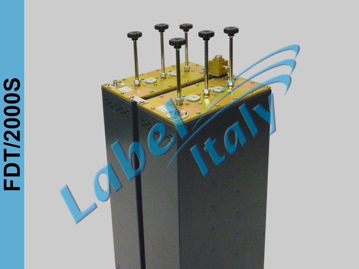
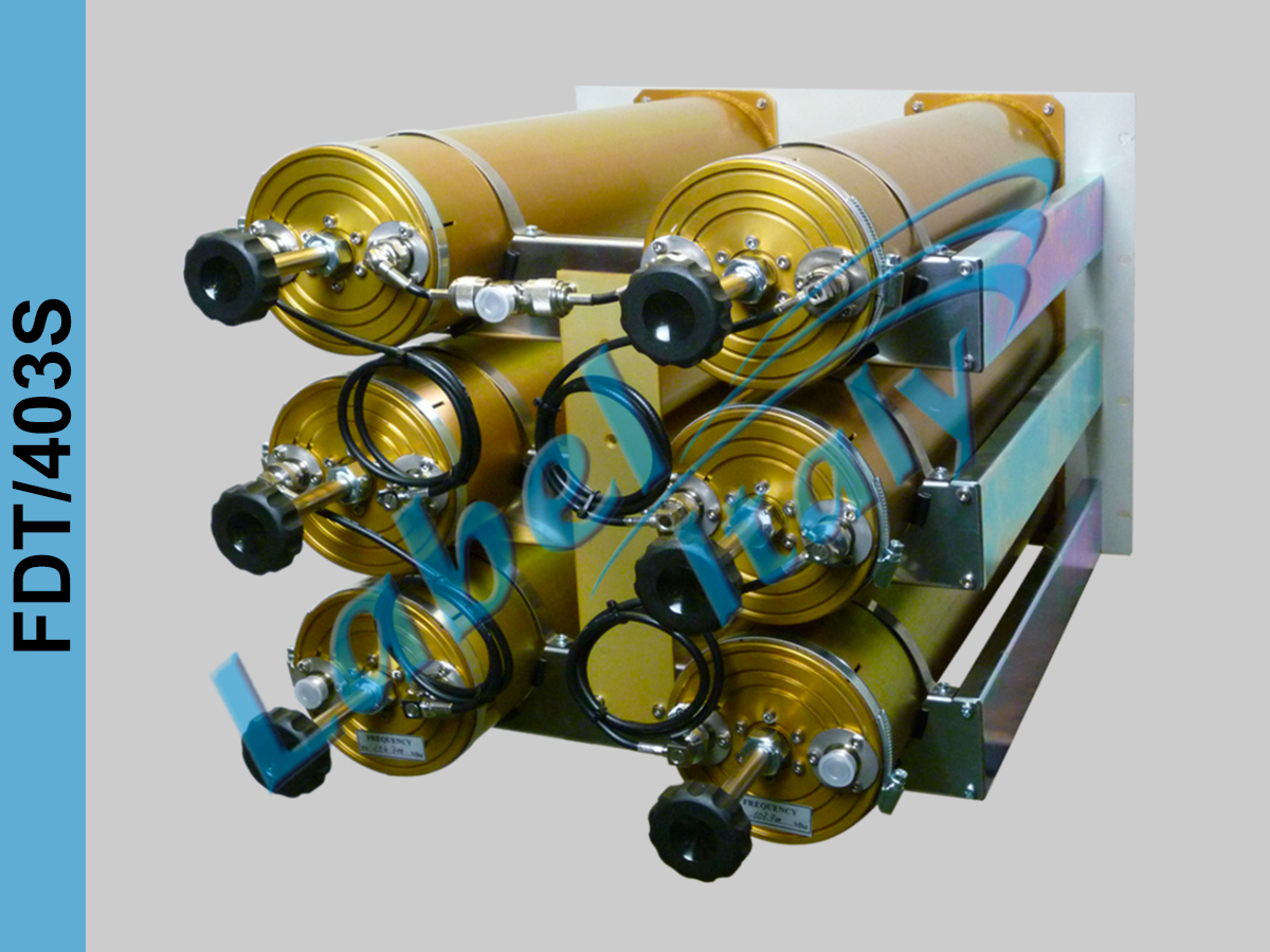
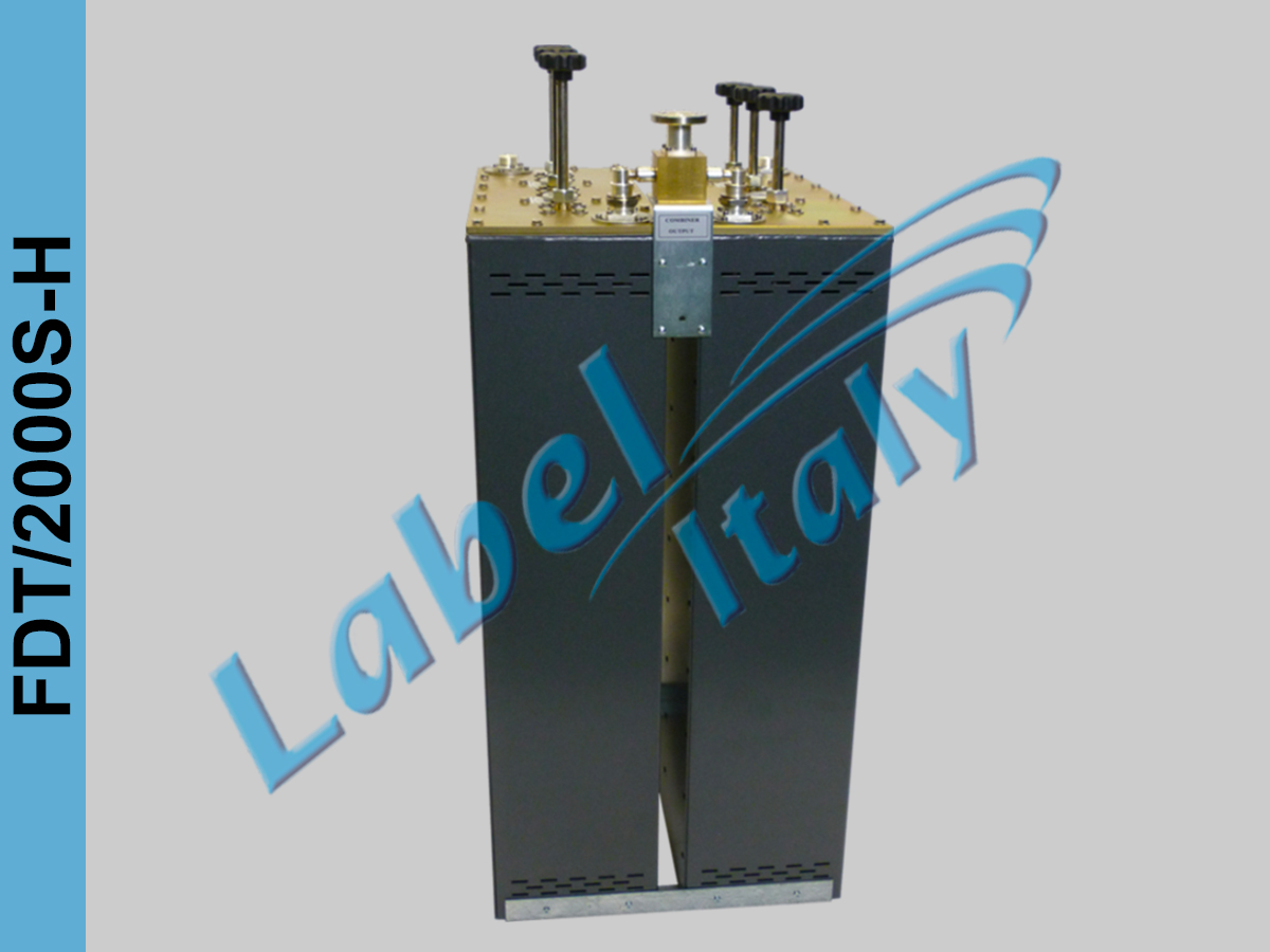
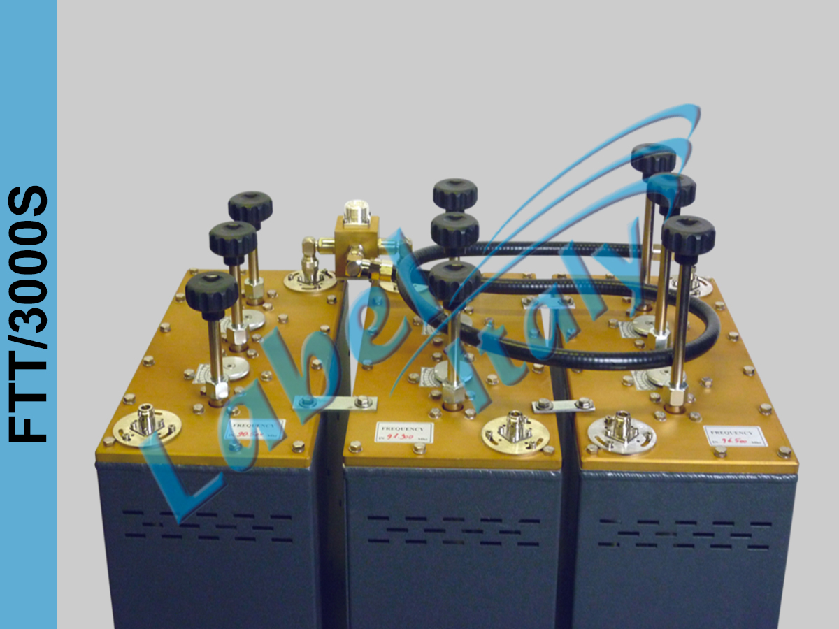
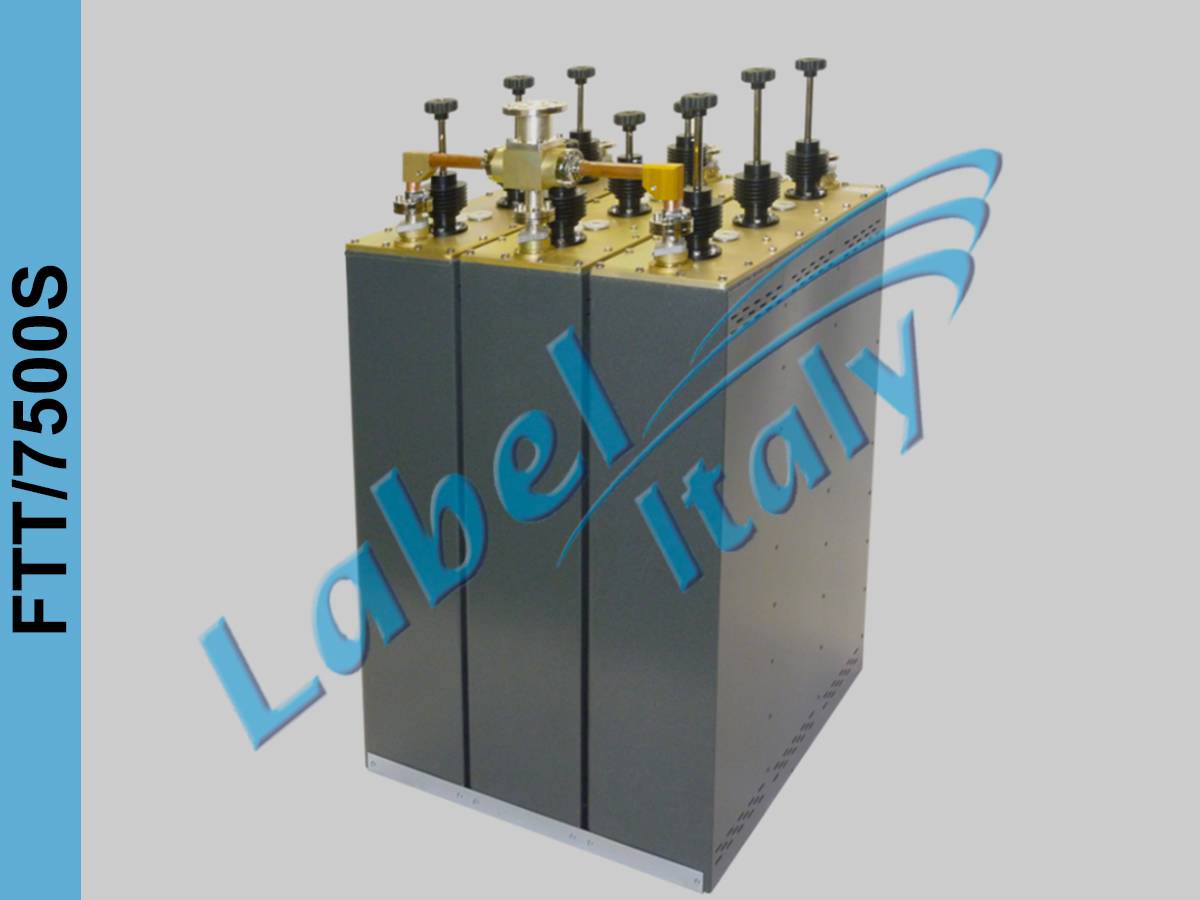
These FM Starpoint Combiners are made of aluminum with internal lines of silvered copper and PTFE insulators.
They are composed of two or more cavity filters connected together by rigid lines, so we will have all inputs selective. For these type of FM starpoint combiners is therefore necessary knowing at the order all the frequencies of use. These versions use Triple cavity filters and allow for reduced channel spacing
Gallery
| FDT/403S | FDT/2000S | FDT/2000S-H | FDT/4000S | FDT/6000S | FDT/10000S | |
|---|---|---|---|---|---|---|
| FREQ. RANGE (Mhz) | 87.5 – 108 | 87.5 – 108 | 87.5 – 108 | 87.5 – 108 | 87.5 – 108 | 87.5 – 108 |
| IMPEDANCE (Ohm) | 50 | 50 | 50 | 50 | 50 | 50 |
| V.S.W.R. | <1.15:1 | <1.15:1 | <1.15:1 | <1.15:1 | <1.15:1 | <1.15:1 |
| ATTENUATION (dB) | < 0.8 | < 0.6 | < 0.6 | < 0.5 | < 0.5 | < 0.5 |
| ISOLATION BETWEEN CHANNELS (dB typical) | 35 | 35 | 35 | 35 | 35 | 35 |
| WORKING TEMPERATURE | 10-40° | 10-40° | 10-40° | 10-40° | 10-40° | 10-40° |
| CONNECTOR IN | N | N | 7/16 | 7/16 | 7/8 | 7/8 |
| CONNECTOR OUT | N | 7/16 | 7/8 | 7/8 | 1+5/8 | 1+5/8 |
| POWER (W) | 2×200 | 2×800 | 2×1200 | 2×2000 | 2×3000 | 2×5000 |
| WEIGHT (Kg) | 31 | 32 | 34 | 52 | 60 | 90 |
| DIMENSIONS (cm) | 80x49x26 | 130x41x40 | 130x41x40 | 130x60x41 | 130x60x41 | 130x73x70 |
TRIPLEXERS:
| FTT/3000S | FTT/3000S-H | FTT/4500S | FTT/7500S | |
|---|---|---|---|---|
| FREQ. RANGE (Mhz) | 87.5 – 108 | 87.5 – 108 | 87.5 – 108 | 87.5 – 108 |
| IMPEDANCE (Ohm) | 50 | 50 | 50 | 50 |
| V.S.W.R. | <1.15:1 | <1.15:1 | <1.15:1 | <1.15:1 |
| ATTENUATION (dB) | < 0.6 | < 0.6 | < 0.5 | < 0.5 |
| ISOLATION BETWEEN CHANNELS (dB typical) | 35 | 35 | 35 | 35 |
| WORKING TEMPERATURE | 10-40° | 10-40° | 10-40° | 10-40° |
| CONNECTOR IN | N | 7/16 | 7/16 | 7/8 |
| CONNECTOR OUT | 7/16 | 7/8 | 1+5/8 | 1+5/8 |
| POWER (W) | 3×500 | 3×1000 | 3×1500 | 3×2500 |
| WEIGHT (Kg) | 60 | 61 | 80 | 81 |
| DIMENSIONS (cm) | 130x62x40 | 130x62x40 | 130x62x60 | 130x62x60 |
QUADRIPLEXERS:
| FQT/4000S | FQT/4000S-H | |
|---|---|---|
| FREQ. RANGE (Mhz) | 87.5 – 108 | 87.5 – 108 |
| IMPEDANCE (Ohm) | 50 | 50 |
| V.S.W.R. | <1.15:1 | <1.15:1 |
| ATTENUATION (dB) | < 0.6 | < 0.6 |
| ISOLATION BETWEEN CHANNELS (dB typical) | 35 | 35 |
| WORKING TEMPERATURE | 10-40° | 10-40° |
| CONNECTORI IN | N | 7/16 |
| CONNECTOR OUT | 7/8 | 1+5/8 |
| POWER (W) | 4×500 | 4×1000 |
| WEIGHT (Kg) | 74 | 75 |
| DIMENSIONS (cm) | 130x90x42 | 130x90x42 |
Peak FM power calculation in multi-frequency systems
The output power of an FM transmitter is basically stable. When two transmitters of different frequencies are combined together, the RF peak voltage will be higher than usually thought.
Supposing to use a 5kW transmitter terminated with a 50 ohm load we will have:
P = V2 / R
V = √ (P x R) = √ (5000 x 50) = 500Vrms
The peak voltage will be √2 x 500V = 707V peak.
By combining two 5kW transmitters in a single output to be sent to the antenna system, the individual voltages must be added together , then doubled, resulting in 1000Vrms or 1414V peak.
The comparison with a single 10kW transmitter, that is the simple algebraic sum of 5 + 5kW, they generate a voltage of 707Vrms or 1000V peak, which however does not correspond to the previous calculation of the two combined transmitters.
To obtain the value of the equivalent power that produces a voltage of 1000Vrms we will have:
P = 10002 / 50 = 20kW
We have therefore that the equivalent power of the combination of 5 + 5kW transmitters will produce the equivalent effect of a single 20kW transmitter and not a 10kW transmitter as is often erroneously taken into account.
In the case of four combined 5kW transmitters they will supply the antenna 4x500V = 2000Vrms.
However, by applying the formula we find that this voltage is equivalent to a single 80kW transmitter and not 5kWx4 = 20kW !
The following formula can therefore be used for transmitters of same power:
Total peak power = Sum of TX powers x number of transmitters
As more transmitters are added, the peak voltage will rise rapidly. This peak voltage is fundamental, especially at high powers with multiple transmitters of different frequencies. The addition of another transmitter is not simply an additional power load. The increase in voltages within the transmission and antenna lines can be significant. If impedance matching is less than perfect, the VSWR will create an even higher peak value.
Coaxial cables that may have been compromised due to humidity or other are more likely to accentuate the problems of higher peak voltage. In the same way, if the antenna is stressed with a power close to its maximum limit, using it with more frequencies, it is very likely a temporary increase in the VSWR, for example during the formation of ice that could start a series of faults in the cables and in the power dividers.
Calculation of nominal power of cables
Cable specifications often provide assessments at various frequencies, but not always at the frequency of interest. Here is a simple formula to obtain from a maximum power expressed at a certain frequency a corresponding to a different frequency:
P2 = P1 / √ (F2 / F1)
P1 = known nominal power
P2 = nominal power at the second frequency
For example, if the cable (or connector) has a nominal power of 5kW at 20MHz, it is possible to calculate its nominal power at 100MHz.
P2 = 5000 / √ (100/20) = 2236 watt
We must not forget that the maximum power borne by the coaxial cables is typically considered for an ambient temperature of no more than 40 ° but unfortunately the cables are outside and usually black, during the day they therefore undergo a strong overheating even just for effect. of solar radiation. To this is added then that generated by the transit of the RF power that due to the losses due to attenuation transforms part of the RF power into heat.
When deciding to use a radiant system connected to a Multiplexer where there are more frequencies and transmission powers, one must never forget to make a thorough evaluation of the effects on connectors, cables, dividers and antennas.
The whole radiant system is therefore stressed more than a single transmitter and therefore must be sized correctly also for the overall reliability.
In this case, a hypothetical failure would result in the loss of service of all the frequencies connected to the radiant system and therefore potentially more serious than in the case of a single transmitter.
It is therefore necessary to provide for a greater safety margin which, for example, can also consist in dividing the radiant system in half and installing two separate feeder cables, so as to be able to use at least half of the antenna even if with less power and therefore not to stop the transmissions and at the same time be able to check the damaged parts.

